Our stories
Connecting experts and enthusiasts, dreamers and doers, innovators and influencers — explore and experience.
Explore our stories
- Listing Title
- Oxygen Sensor Tech Tips
- Listing Subtitle
- Products | O2
- Listing Image
-
- Article Title
- Oxygen Sensor Tech Tips
- Article Subtitle
- Knowing which Sensor to Change
- Article Image
-
- Summary
Because engine configurations can vary by vehicle, it’s important to correctly identify the specific positions of all your oxygen sensors – so you replace the correct sensor when one of them fails. The post below provides some guidance in understanding which oxygen sensor to change and a few technical tips to assist in a smooth installation process.
Sensor Locations
Refer to your vehicle service manual to determine your sensor locations. If the manual is not available, here are some guidelines that apply to most vehicles:
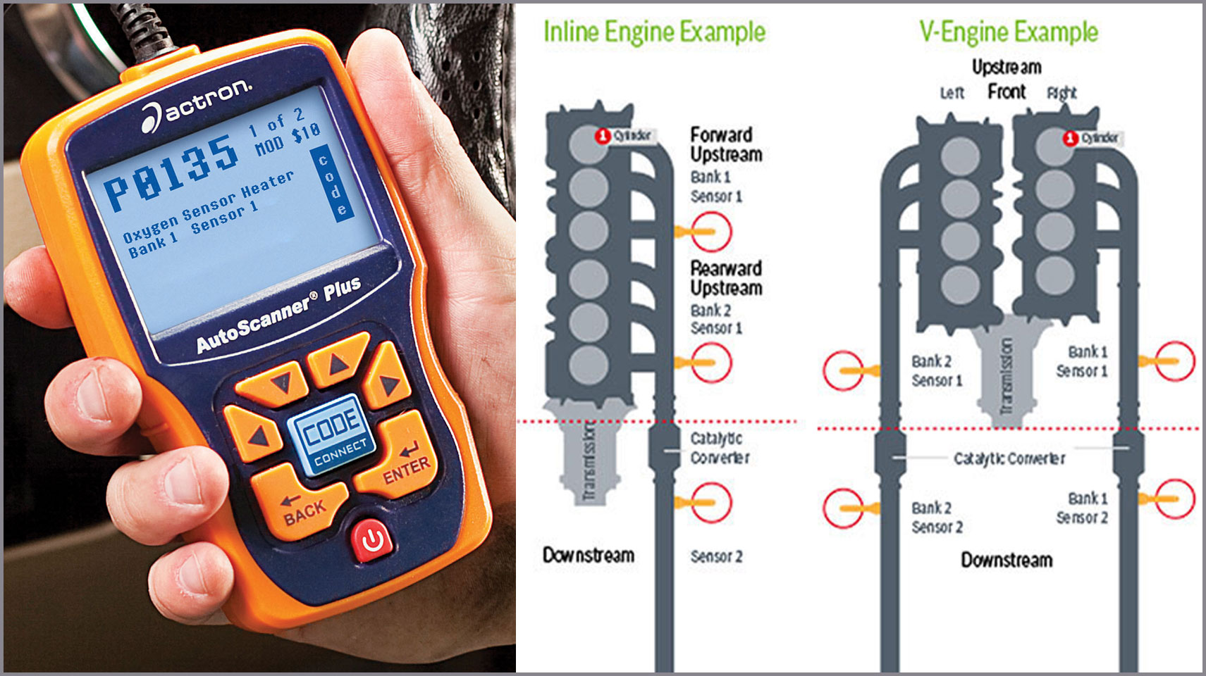
Location by Code

- Car makers generally define Bank 1 as the Bank containing Cylinder 1.
- If you don’t know your Cylinder 1 location, ask your auto parts store associate for a cylinder-number- or firing-order diagram for your vehicle. See example at right.
- Sensor 1 is the upstream sensor and Sensor 2 is generally located after the catalyst (downstream)
- On a 3 sensor per bank system, Sensor 2 is located on the catalyst and Sensor 3 is located after the catalyst.
Catalog Locations
- The front of the engine contains the belt and alternator.
- The transmission is mounted to the rear of the engine.
- Left and right are defined looking from the rear to the front of the engine.
- On rear wheel drive applications, this is the view from the drivers seat.
- Use the bank detail (at left) to determine if you need a forward, rearward, left or right sensor.
- Car makers generally define Bank 1 as the Bank containing Cylinder 1.
- Section 1 Title
- Installation Tip
- Section 1 Image
-
- Section 1 Body
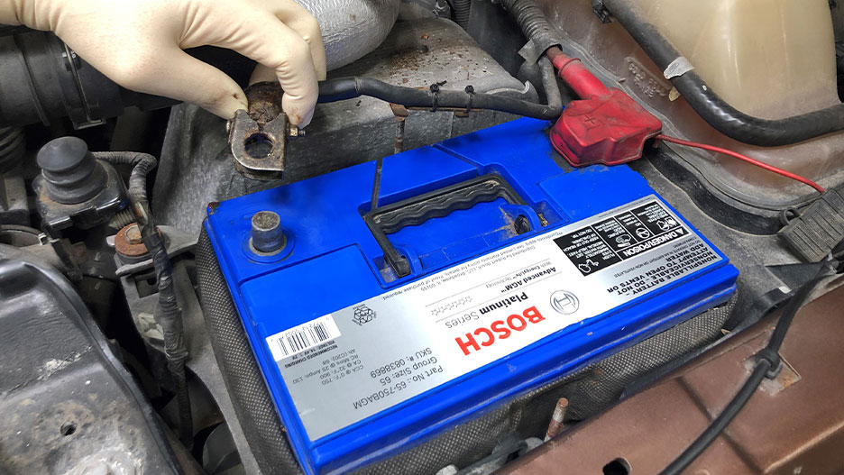
Disconnect the Battery
Many vehicles require a sensor learning trigger from a scan tool after a new sensor is installed. Clearing codes does not initiate this learning process, but often a 5 minute battery disconnect can. So, not only is having the battery cable disconnected during service recommended for safety, it can also help you avoid unnecessary service.
- Section 2 Title
- Reference Air
- Section 2 Image
-

- Section 2 Body
Because Oxygen Sensors require a clean reference air sample to function properly:
- It’s critical that the wiring harness is not damaged during installation.
- The use of dielectric grease, cleaners and other chemicals in the connector or on the sensor can cause permanent damage.
- Section 3 Title
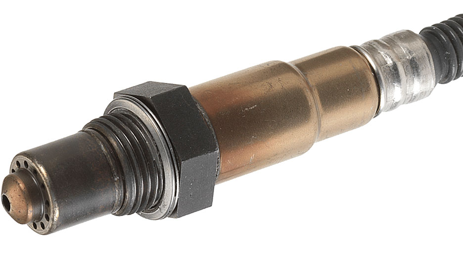
- Discolored / Seared Protection Tube Ensures High Quality
- Section 3 Image
-
- Section 3 Body
Some customers have noticed a dark discoloration on Bosch sensors and question if the part is used.
- Rest assured that this discoloration is normal and the result of one of many processes we utilize during manufacturing to ensure quality and performance.
- Section 4 Title
- Section 4 Image
- Section 4 Body
- Section 5 Title
- Section 5 Image
- Section 5 Body
- Section 6 Title
- Section 6 Image
- Section 6 Body